1、MSD (Manual Service Disconnector)
3、Terminal and Back Cover Installation
The MSD (Manual Service Disconnector), also known as the manual service disconnector, is primarily used in power battery systems. In emergencies or during battery maintenance or installation, the MSD can be disconnected immediately, disconnecting the battery pack current and protecting personnel.
Product Cable Outlet:
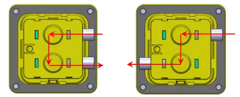
The product features flexible cable outlets that can be routed from one side or both. Please confirm the orientation before use.
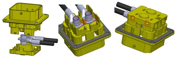
Installing the crimped terminals into the base, ensuring they snap into place. Then, replace the back cover, ensuring the four back cover clips snap into place.
Place the product with the black gasket on the panel with the hole and tighten with four M6 bolts. Connect the two cables of the high-voltage interlock switch to the control system.
For waterproofing, ensure that the four bolts are installed with O-rings.
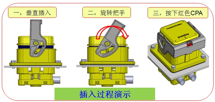
4.1. The handle must be in a vertical position during insertion to prevent damage to the product if it is not fully seated.
4.2. Rotate the handle to a horizontal position; you will hear a click.
4.3. Press the red CPA down until it fits snugly against the handle.
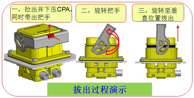
a. After removing the CPA, push down on it and remove the handle.
b. Rotate the handle to a vertical position.
c. Pull out the male end of the product.
a. The black sealing gasket not only provides waterproofing during installation but also acts as a shock absorber. Please ensure it is installed.
b. During installation, ensure that the terminals with wires are free to prevent stress and twisting of the wires during installation, which could damage the product.
c. The high-voltage interlock protects the entire system. Ensure it is installed and functioning properly before use.
d. After installation, ensure that the CPA is fully seated. Avoid leaving it partially or partially seated, which could affect product functionality.