
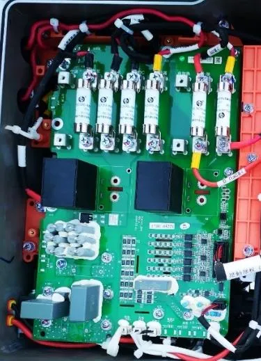
1.1.High-Voltage Power Distribution
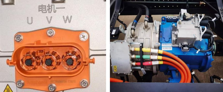
1.2.Main Drive Motor Controller
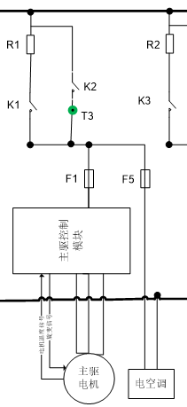
3、Control logic Main drive contactor (K1, K2)
3.1.Main drive contactor energization conditions in driving state
3.3.K2 disconnection condition
3.4.After K2 is energized, the energization status message is fed back to the HCU
4、Upper load contactor (K3, K4)
4.1.Upper load contactor energizing condition
4.2.K4 disconnection condition
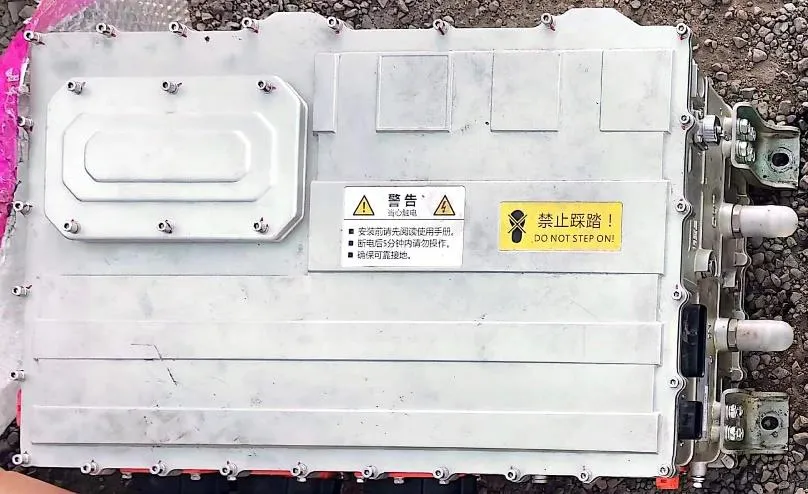
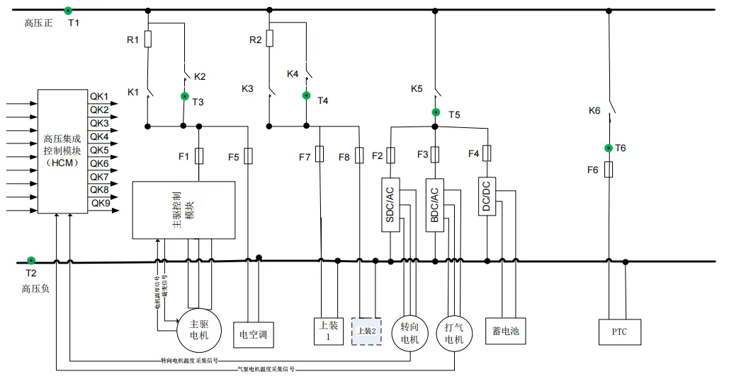
This module integrates contactors, fuses, and other components into a compact, independent module. Compared to discrete components built with cables, this module is smaller, easier to assemble, and offers more stable performance. It includes the pre-charge circuit, main positive circuit, high-voltage accessory circuit, charging circuit, and components for each circuit: contactors, fuses, busbars, cables, etc. It distributes and protects the high-voltage main circuit (motor controller) and high-voltage auxiliary circuits (air compressor, DC/DC converter, electric steering controller, air conditioning compressor, PTC). Fuses are also reserved for the mainframe to provide high-voltage power.
This module provides power for the vehicle. The motor controller converts high-voltage DC power into three-phase AC power for the drive motor, which then outputs torque through the gearbox to propel the vehicle.
Steering Pump Controller: This module provides steering assistance for the vehicle.
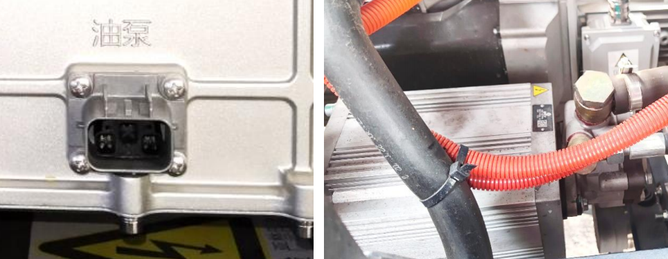
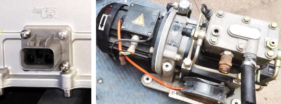
The steering pump controller (DC-AC inverter) converts high-voltage DC power into three-phase AC power to supply the steering pump motor. The motor drives the steering oil pump to generate oil pressure, thereby achieving the function of power steering. The air pump DCAC module is a control module that provides power for the entire vehicle's braking. The air pump controller (DC-AC inverter) converts high-voltage DC power into three-phase AC power to supply the air pump motor. The motor drives the air pump to generate compressed air, thereby achieving the function of power braking.
The DCDC module converts high-voltage DC power into low-voltage DC power to charge the vehicle's low-voltage battery and provide a stable low-voltage power supply for the vehicle's low-voltage electrical appliances.
① Power-on enable signal
② On gear signal
③ Start gear signal When the three signals are valid at the same time, the main drive contactor energizing process is executed.
When signals ① and ② exist at the same time, K2 is maintained in the energized state.
Signals ① and ③ are CAN signals sent by the HCU, and ② is a hard-wired signal.
The condition is whether the A+ signal is valid. When it is valid, K2 is not allowed to energize.
No ① or ② and the controller internal judgment.
①K2 energizing signal
② Upper load start signal
③ Upper load enable signal When ①②③ are valid at the same time, the upper load contactor energizing process is executed.
When signals ①②③ exist at the same time, K4 is maintained in the energized state.Signals ②③ are hard-wired signals sent.
No ②③ and when K2 is normally disconnected, the upper load contactor must also be disconnected.