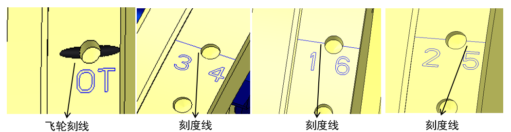
1、WP13SNG Youshun Brake Valve Clearance Adjustment Method
1.1 Facing the flywheel, turn the flywheel counterclockwise from the OT line to the mark "1 6" on the outer edge of the flywheel. Check whether the intake clearance of cylinder 1 is adjustable. If so, adjust the intake valve clearance of cylinders 1, 4, and 5 by 0.5mm, and the exhaust valve clearance of cylinders 1, 3, and 5 by 0.8mm. Use the dedicated tool to adjust the brake rocker arm clearance of cylinder 6 to 2.8mm. If the intake clearance of cylinder 1 is not adjustable, proceed directly to step d to adjust the clearance, then push forward.
1.2 Facing the flywheel, turn the flywheel counterclockwise to the mark "2 5" on the outer edge of the flywheel. Use the dedicated tool to adjust the brake rocker arm clearance of cylinder 2 to 2.8mm.
1.3 Facing the flywheel, turn the flywheel counterclockwise to the mark "3 4" on the outer edge of the flywheel. Use the dedicated tool to adjust the brake rocker arm clearance of cylinder 4 to 2.8mm.
1.4 Turn the flywheel counterclockwise facing the flywheel to the "1 6" mark on the outer edge. Adjust the intake valve clearance of cylinders 2, 3, and 6 by 0.5mm. Adjust the exhaust valve clearance of cylinders 2, 4, and 6 by 0.8mm. Use the dedicated tool to adjust the brake rocker arm clearance of cylinder 1 to 2.8mm.
1.5 Turn the flywheel counterclockwise facing the flywheel to the "2 5" mark on the outer edge. Use the dedicated tool to adjust the brake rocker arm clearance of cylinder 5 to 2.8mm.
1.6 Turn the flywheel counterclockwise facing the flywheel to the "3 4" mark on the outer edge. Use the dedicated tool to adjust the brake rocker arm clearance of cylinder 3 to 2.8mm.