1、Charging connector insulation problem
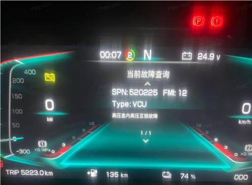
3、Unable to supply high voltage-the instrument prompts
The specific cause of the charging port failure can be identified according to the diagram. The specific operations are as follows: For some charging reports of insulation, NTC abnormality, communication abnormality, no charging icon when plugging in the gun, single gun cannot be charged but dual guns can be charged, and insufficient charging current, it is necessary to check whether the two low-voltage connectors behind the charging socket have water ingress, looseness, or pushed pins.
the instrument prompts NTC failure. The charging socket NTC failure refers to the failure of the charging socket's internal temperature sensor, resulting in charging failure. The main reasons are failure of the NTC itself and abnormal BMS motherboard hardware.
① Turn off the power to the vehicle
② Check whether the low-voltage connector of the charging socket has water ingress, pushed pins, etc.;
③ Use a multimeter to measure the 12-pin low-voltage connector at the rear end of the charging socket;
④ Find the corresponding pin to measure the resistance, which should be around 10K at room temperature. If the deviation is large, replace the charging socket;
⑤ There are a total of 4 NTCs, measure all of them. If they are all normal, it may be that the BMS mainboard is abnormal, and replace the mainboard.
① If only one path is disconnected, you can temporarily connect them in parallel (temporary measure);
② Replace the charging socket
③ Clean the charging socket plug and do a waterproof treatment
④ Replace the BMS mainboard;
① Power off the system (key off)
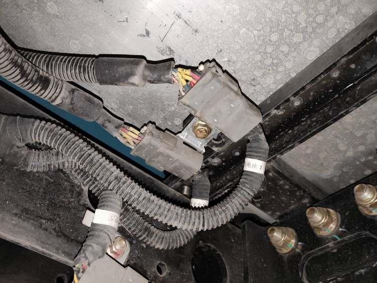
② Check whether the MSDs are all plugged in, whether the MSD buckle is locked, whether the MSD interlock pins are skewed or abnormal, and re-tighten them;
③ Power on the system to see if it returns to normal; If not, power off the system and continue with the following operations; ④ Remove the outer covering or disassemble the housing of the high-voltage box.
⑤ Check that all high-voltage connectors inside the high-voltage box are secure (on both the front and rear sides). Ensure that properly inserted quick-release plugs and sockets fit snugly and securely, with the upper latch locking the socket securely in place and the latch flush with the outer extension.
⑥ Locate any loose plugs, take photos, and re-seat them.
⑦ Re-power on to see if the problem is resolved. If the fault persists, it may be due to poor contact in the low-voltage interlock signal connector inside the high-voltage box.
0 4 Unable to apply high voltage - The instrument indicates that the main negative relay is stuck. Sticking occurs when the main output relay is stuck and cannot disconnect. Causes include on-load connection, on-load disconnection, abnormal disconnection of the low-voltage power supply, relay overcurrent, BMS software issues, installation problems, or relay quality issues.
① Remove the VCU fuse.
② Measure the voltage between DC- and PE at the charging port with the power turned on. If a stable voltage of approximately 300V is present, a sticking problem is confirmed.
③ Alternatively, measure the total voltage of the discharge circuit when the power is turned on. If there is a stable voltage of around 614V, it can be determined that there is a adhesion problem.