4、System Structure and Principle
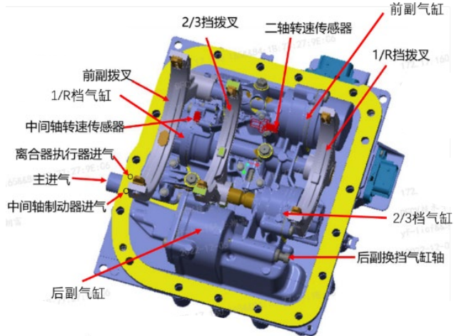
The cylinder assembly is responsible for the shifting action execution of the entire transmission assembly;
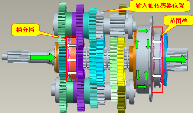
It is mainly divided into four parts: front auxiliary, 1/R, 2/3, and rear auxiliary.
| Serial number | Name | Serial number | Name |
| 1 | Countersunk bolt | 2 | Magnetic block |
| 3 | Piston 1 | 4 | Neutral limit block |
| 5 | Piston 2 | 6 | Piston 3 |
| 7 | Self-locking pin | 8 | Shift fork shaft |
| 9 | Magnetic block bolt | 10 | Split pin |
| 11 | Shift fork |
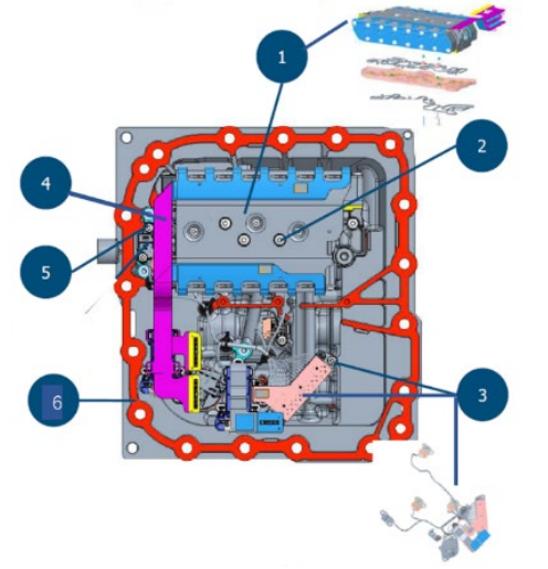
Solenoid valve sensor assembly Serial
| Serial number | Name | Serial number | Name |
| 1 | Solenoid valve group | 2 | Solenoid valve fixing bolt |
| 3 | Sensor assembly | 4 | Soft row |
| 5 | Countersunk bolt | 6 | Sealing gasket |
The solenoid valve group is responsible for the command of the actuator TCU, giving the shift actuator each cylinder intake and exhaust, clutch actuator intake and exhaust, and intermediate shaft brake intake and exhaust
The sensor group is responsible for sensing the position signal of each cylinder, intermediate shaft/spindle speed signal, oil temperature signal and intake pressure signal, and feeding them back to TCU
| No. | Name | No. | Name |
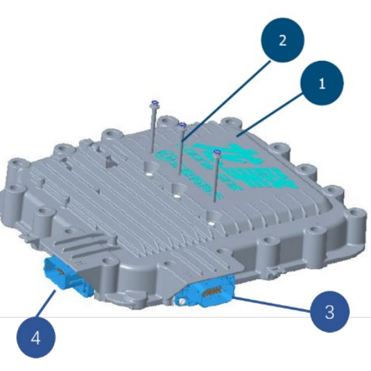
| 1 | Top cover with TCU assembly | 2 | Top cover mounting bolts |
| 3 | X1 - Vehicle end | 4 | X2 - Clutch end |
X1 connects to the vehicle power supply and CAN network, and X2 connects to the clutch actuator sensor for external communication.
Internal Connections:
Internal communication is achieved through onboard connectors and a flexible busbar connecting the solenoid valve group and sensor group.
AMT Clutch System Structure and Principle
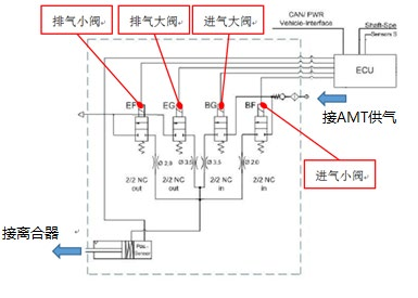
The clutch system primarily consists of the clutch solenoid valve group, clutch actuator, and clutch assembly. The solenoid valve group is integrated into the valve island inside the transmission top cover and consists of four solenoid valves.
There are two exhaust valves and two intake valves, one large valve and one small valve, respectively, for fast clutch control and slow clutch control.
System Operating Principle:
When the clutch system is operating, the clutch solenoid valve assembly receives status requests from the TCU and opens or closes the corresponding solenoid valves. Compressed air enters or exits the clutch actuator cylinder, causing the clutch actuator piston to move forward or backward, driving the release fork, thereby disengaging or engaging the clutch assembly and enabling vehicle functions such as starting, stopping, shifting, and creeping.
The displacement sensor collects real-time displacement information required for closed-loop control and feeds it back to the TCU for clutch displacement closed-loop control.
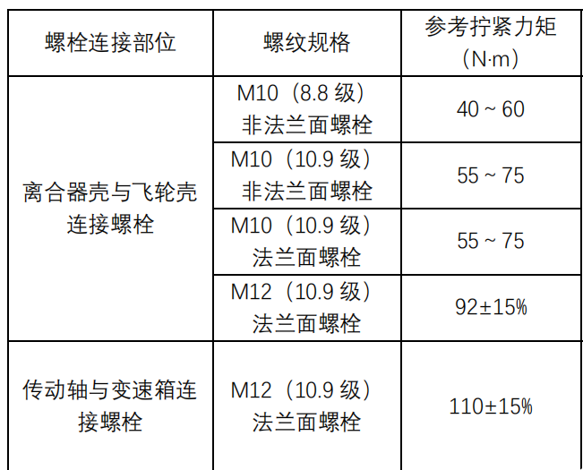
Transmission Main Bolt Tightening Torque Chart.
However, when learning to repair a transmission, we often encounter the following questions:
What is the data flow for each gear?
When encountering a fault, how can we accurately identify the problem and implement the correct repair method?
What is the transmission shift logic?
With the increasing demand for AMT repairs, repair technicians with little foundation, understanding, or experience are facing challenges.
A systematic and comprehensive AMT repair training course is particularly important. It goes beyond simply imparting a single knowledge point, providing comprehensive and systematic instruction.
Covers AMT gear data flow explanation,
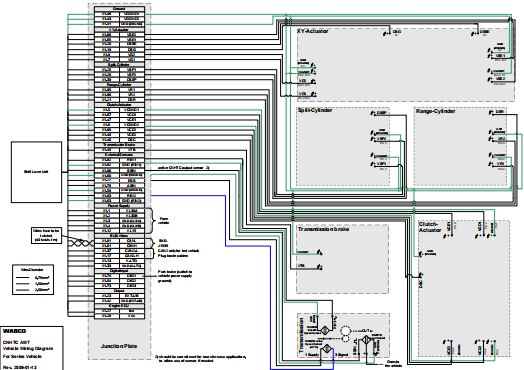
AMT circuit diagram reading,
AMT shift logic explanation,
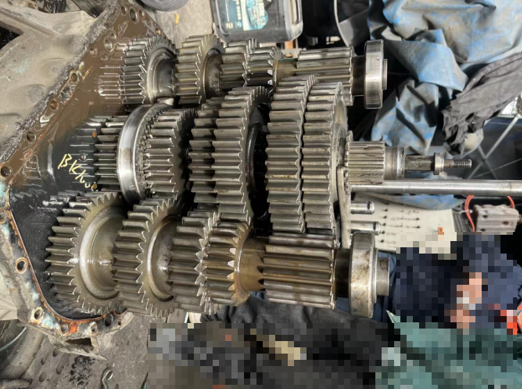
on-site disassembly and assembly
... Also, common AMT gearbox failure cases and solutions...
END Free collection of various maintenance materials, engine maintenance manual, conventional brake electronic data, AMT gearbox maintenance manual, manual gearbox maintenance manual, ABS, EBS electronic data.