1、Motor Insulation Measurement Method
1.1.Use a dedicated insulation meter with the black
1.2.Generally, a qualified insulation resistance of 100MΩ is displayed
| Requirements | Standard | Equipment |
| Phase-to-Ground 500VDC Insulation Resistance | >100MΩ | Insulation Meter |
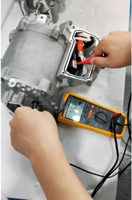
Use a dedicated insulation meter with the black test lead connected to ground and the red test lead connected to a resolver pin. Then press and hold the TEST button to test the three-phase (U, V, W), sine, cosine, excitation, NTC1, and NTC2 insulation. The standard is ≥100MΩ @ 500VDC.
| No. | Measurement Location | Standard | Equipment |
| 1 | NTC 1, NTC 2, ground insulation | ≥100 MΩ @ 500 VDC | Insulation Meter |
| 2 | Resolver: Sine, cosine, excitation ground insulation | ≥100 MΩ @ 500 VDC | Insulation Meter |
| 3 | Three-phase U, V, W ground insulation | ≥100 MΩ @ 500 VDC | Insulation Meter |
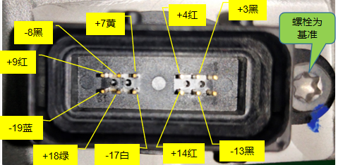
Set the meter to the ohm range. Check the units in the upper right corner of the screen: MΩ, Ω, KΩ, diode; for CMA motor resolver resistance, select Ω.
Use a dedicated multimeter and connect the black and red test leads to the sine (positive and negative) poles, cosine (positive and negative) poles, and excitation (positive and negative) poles, respectively, to measure the sine, cosine, and excitation resistance values.
| (P3)Motor electrical performance test - standard |
| Serial number | Measurement position | Standard |
| 1 | Low voltage connector pin pin rotary variable resistance excitation (11, 12) | 24.3-29.7Ω@25℃ |
| 2 | Low voltage connector pin pin rotary variable resistance SIN (9, 10) | 54-56Ω@25℃ |
| 3 | Low voltage connector pin pin rotary variable resistance COS (7, 8) | 57.6-70.4Ω@25℃ |
| (M4)Motor electrical performance test - standard |
| Serial number | Measurement position | Standard |
| 1 | Low voltage connector pin pin rotary variable resistance excitation (11, 12) | 24-30Ω@25℃ |
| 2 | Low voltage connector pin pin rotary variable resistance SIN (9, 10) | 57-71Ω@25℃ |
| 3 | Low voltage connector pin pin rotary variable resistance COS (7, 8) | 45-66Ω@25℃ |
| (G7) Motor electrical performance test - Standard |
| No. | Measurement position | Standard |
| 1 | Low voltage connector pin pin resolver resistance excitation (11, 12) | 20.6±2Ω@25℃ |
| 2 | Low voltage connector pin pin resolver resistance SIN (9, 10) | 49.8±5Ω@25℃ |
| 3 | Low voltage connector pin pin resolver resistance COS (7, 8) | 55.3±5Ω@25℃ |