1、IGBT Drive Circuit for Pure Electric Vehicles
In a pure electric vehicle's IGBT drive circuit, the IGBT is divided into an upper bridge and a lower bridge. To use a digital multimeter to measure the three electrodes of the IGBT and the upper and lower bridge arms, we first need to understand its basic circuit structure.
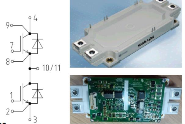
To determine the voltage between pins 3 and 4 of the IGBT, we can use the series connection of diodes and their forward voltage drop. As shown in the figure, pin 4 is connected to the DC+ supply of the power battery, and pin 3 is connected to the DC supply of the power battery.
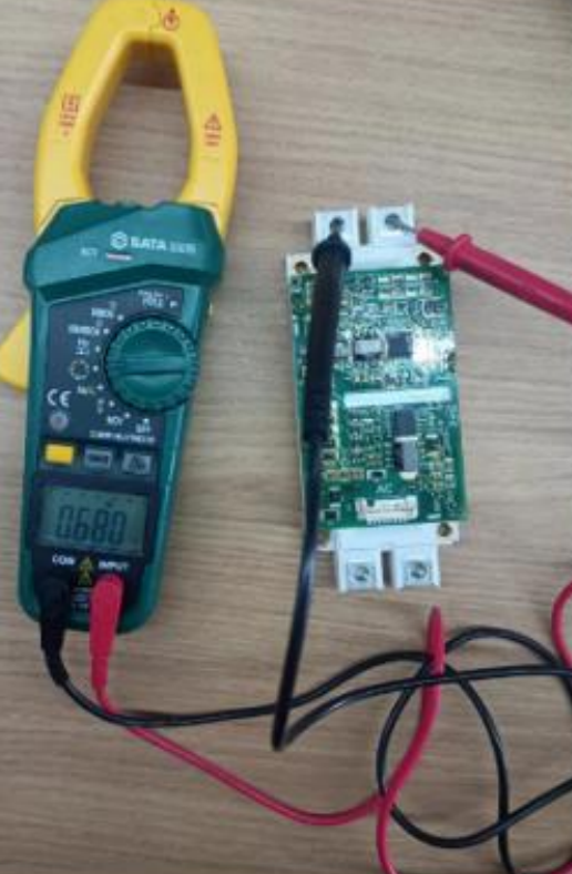
The measured voltage drop is 0.68V, indicating that the red test lead is connected to pin 3 of the IGBT and the black test lead is connected to pin 4 of the IGBT. We also know that pin 3 is the emitter of the lower bridge arm and pin 4 is the collector of the upper bridge arm.
The emitter of the upper bridge arm and the collector of the lower bridge arm are connected together and output as one phase of the three-phase AC power. This is measured using a multimeter.
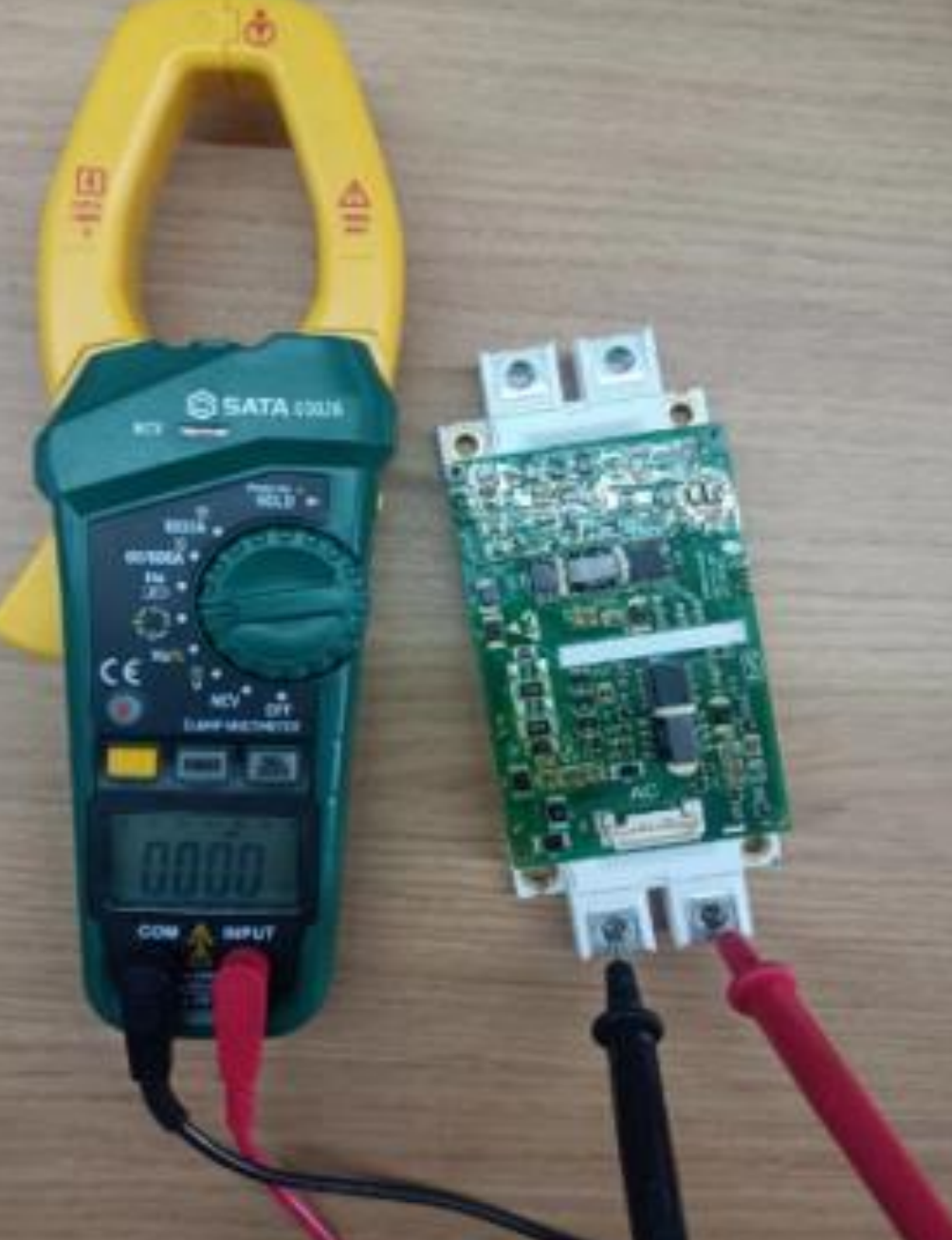
The measured voltage drop is 0V, indicating that the emitter of the upper bridge arm and the collector of the lower bridge arm are together, and the output is a single-phase alternating current.