1、Basic Structure and Function of the Electric Drive System
2、Drive Motor Signal Terminal Definitions
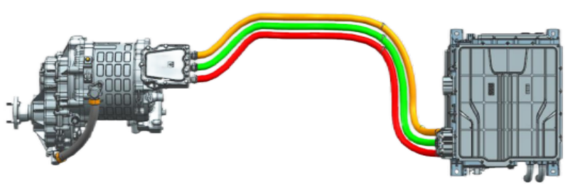
The electric drive system converts electrical energy from the power battery into mechanical energy based on drive commands from the VBU. It primarily consists of a motor controller and a drive motor (including a reducer).
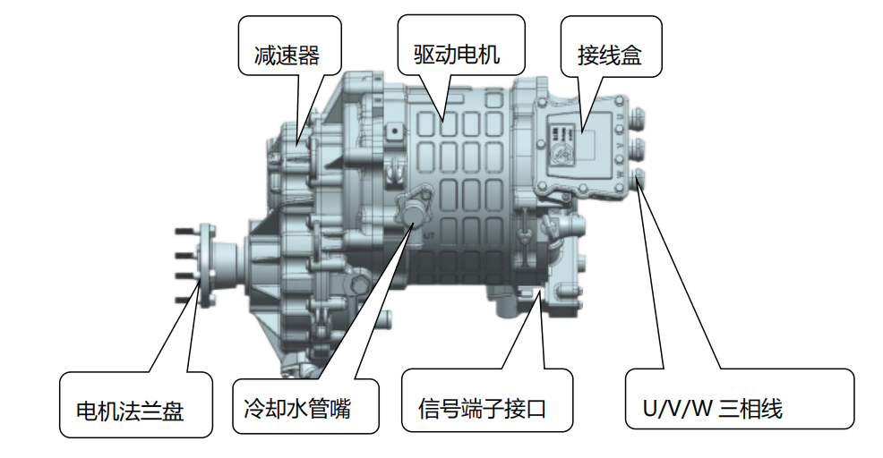
The drive motor is the power unit of new energy electric vehicles. Its function is to convert electrical energy into mechanical energy, generating motive power, which is then used to drive the wheels through the chassis' drivetrain, enabling the electric vehicle to move.
The drive motor consists of key components such as the stator assembly, rotor assembly, motor shaft, front and rear end covers, water-cooling housing, bearings, resolver sensor, and reducer.
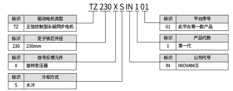
Nameplate
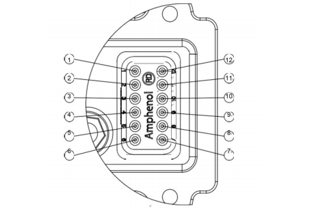
| No | Signal | Remarks |
| 1 | Sin+ | Resolver output sine signal |
| 2 | Cos+ | Resolver output cosine signal |
| 3 | PT1+ | Motor temperature sensor 1 input |
| 4 | PT2+ | Motor temperature sensor 2 input |
| 5 | EXC+ | Resolver excitation signal input |
| 6 | Null | Reserved |
| 7 | Null | Reserved |
| 8 | EXC- | Resolver excitation signal output |
| 9 | PTC2- | Motor temperature sensor 2 output |
| 10 | PT1- | Motor temperature sensor 1 output |
| 11 | Cos- | Resolver output cosine signal |
| 12 | Sin- | Resolver output sine signal |
3.1 Power off the vehicle, turn off the low-voltage main switch, unplug the maintenance switch (quick disconnect), and wait 15 minutes.
3.2 Remove the water pipes and clean the coolant in the motor until no coolant flows out. Avoid splashing coolant onto the connectors.
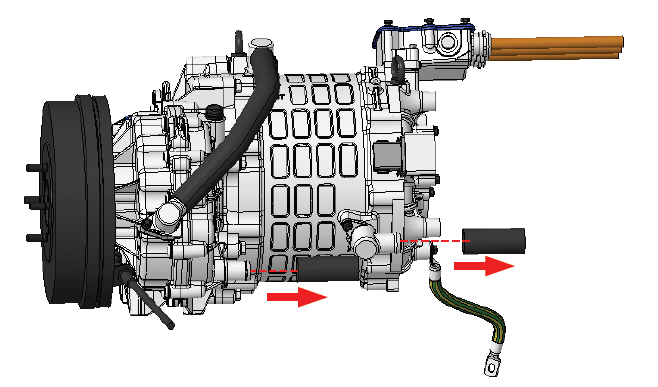
3.3 Unplug the low-voltage cable (12-pin signal terminal block). The connector has snaps at the top and bottom. Push it slightly inward, then grasp the top and bottom ends to remove it.
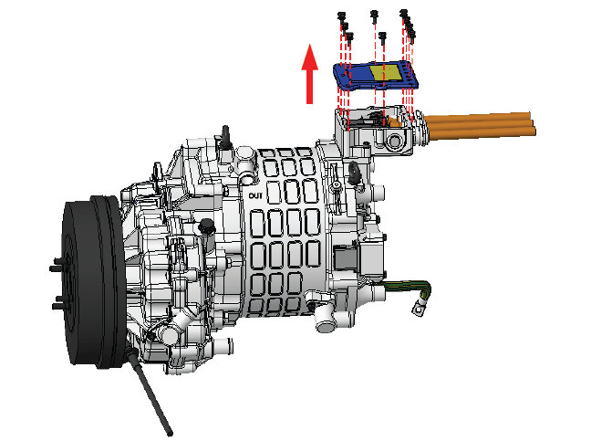
3.4 Remove the junction box cover: Remove the nine M6 hexagonal screws (with spring washers) on the junction box cover.
3.5 Use a multimeter to measure the voltage at the U, V, and W input terminals to ensure that any residual charge is dissipated (i.e., within the human safety voltage range, less than 36V).
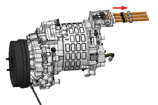
3.6 Remove the screws from the motor's U, V, and W three-phase power wiring terminals: Remove the three M8 hexagonal flange screws at the motor terminal blocks.
3.7 Remove the waterproof plug cap: Use a dedicated wrench to remove the waterproof plug cap. It is recommended to use two wrenches: one to hold the waterproof plug seat and the other to remove it.
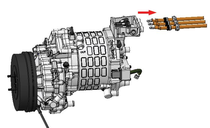
3.8 Remove the power cables and wrap the cable crimping terminals with protective wrap to prevent coolant from splashing during removal.
3.9 Remove the ground wire: Use an electric screwdriver to loosen the M6 spring washer combination screw at the ground bolt and remove the ground wire.
3.10 Under the trench, remove the M12 bolts connecting the accelerator to the vehicle's drive shaft, disconnecting the high-speed single-reduction assembly from the vehicle.
3.11 Remove the assembly's mounting bolts. Before disassembly, support the single-reduction assembly with a hoist to prevent damage from falling. Use a 19mm socket to remove the eight M12 spring-washer screws securing the assembly brackets (for the reducer and motor mounts, see the diagram) and the securing wire.
3.12 Slowly lower the lift and remove the assembly equipment to complete disassembly.