1、Charging Connector Insulation Issue
2、Charging Port Thermistor Issue
3、Charging port communication failure
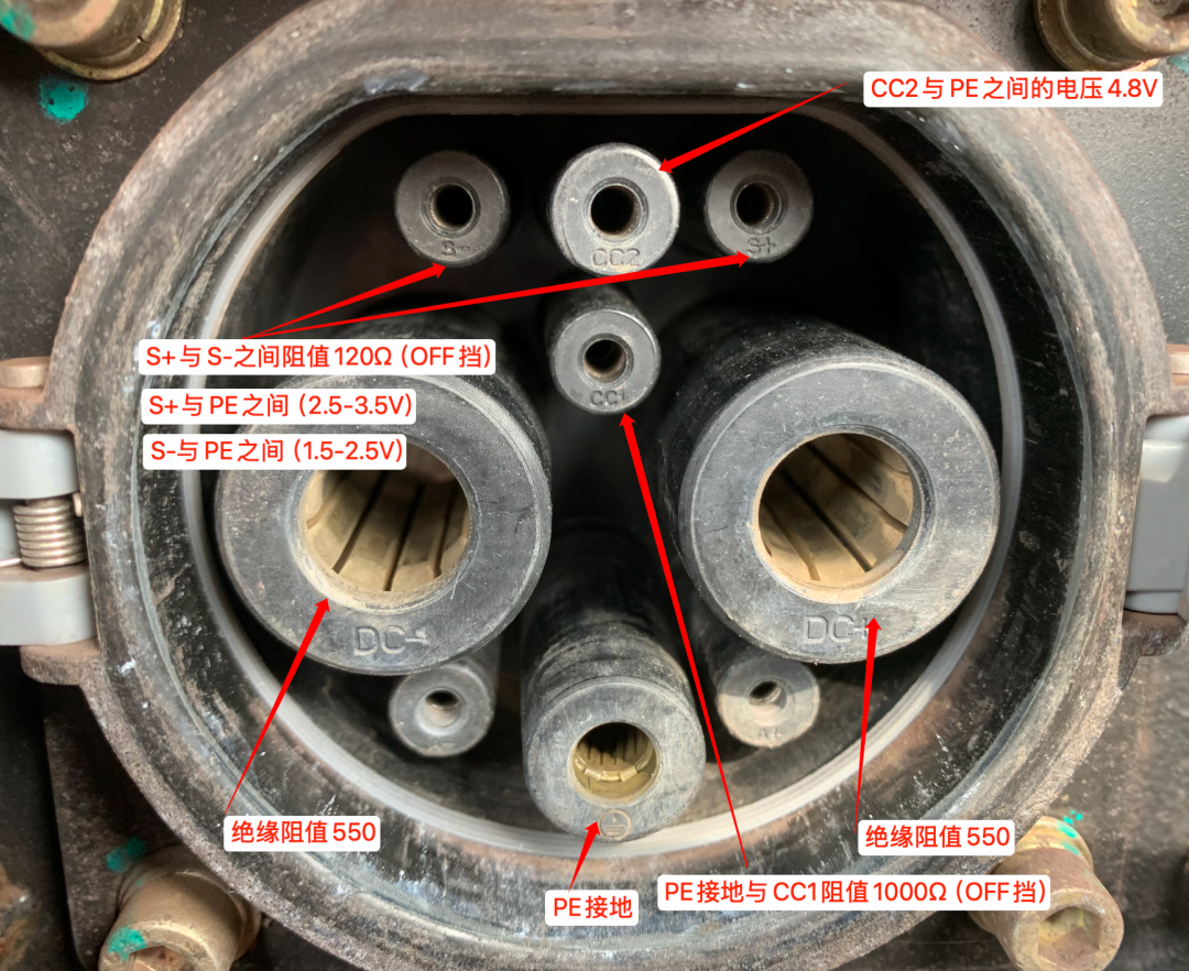
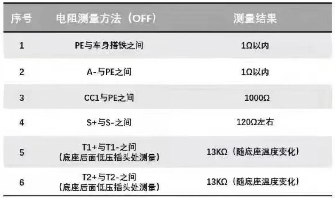
Set the insulation meter to 500V, insert the black lead into the PE terminal of the charging port, and the red lead into the DC+/DC- terminals of the charging port, respectively. Measure the insulation resistance. The correct insulation resistance value is 550 megohms. (In practice, charging can be started as long as the resistance is greater than 100 megohms.)
If the measured value is abnormal, it is usually caused by water ingress into the charging port. Use a vent to blow out the water stain inside the charging port and observe for 2-3 days. If the problem persists, replace the corresponding charging connector.
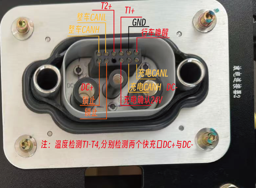
Use a multimeter and set the multimeter to the resistance setting. Follow the charging port connector back to the low-voltage wiring harness. There is a corresponding temperature control resistor harness, labeled T1+/T1-, T2+/T2-, T3+/T3-, and T4+/T4-. Measure the resistance between each pair of wires.
Common resistance values range from 3 to 150 kilo-ohms. If the resistance is incorrect, the connector temperature control resistor or the entire wiring harness needs to be replaced. A temporary solution is to short-circuit the temperature control resistor and short-circuit the wiring harness with abnormal resistance to the wiring harness with normal resistance.
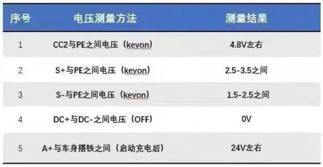
Select a multimeter, set the appropriate setting, and measure the charging port values in sequence. Note that when measuring ground resistance, measure the charging port PE to the vehicle frame or the bolts securing the charging port (pay attention to ensure the grounding bolts are tightened properly). After measuring resistance, measure continuity. When measuring the voltage between CC2 and PE, measure with the key turned on. The voltage between A+ and A- is measured while the vehicle is started and charging. The S+, S-, A+, and A- connections between charging ports 1 and 2 are all connected.