1、Retarder Temperature Sensor Fault Description
1.1.Sensor Electrical Fault Detection
1.2.Sensor Mechanical Damage Diagnosis Criteria
2、Retarder Proportional Valve Fault
2.1.744-2. Proportional Valve Electrical Fault Inspection
3、Retarder Pressure Sensor Fault
3.1.Sensor Electrical Fault Inspection
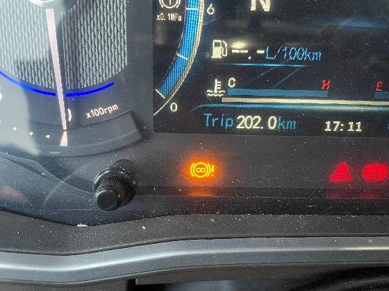
The retarder fault light on the instrument panel is on, and the EOL diagnostic tool reads the following fault codes:
Fault Code:
SPN3001 - Water Temperature Sensor Fault (Only 50% of the braking torque can be used)
Fault Code:
SPN3002 - Oil Temperature Sensor Fault (Full braking torque can be obtained; unlimited torque)
Note: If both sensors report an error at the same time, there will be no braking torque.
Note: If both sensors are connected incorrectly, there will be no fault, but the retarder will operate briefly before exiting the reciprocating cycle.
The retarder temperature sensor is a positive temperature coefficient thermistor, whose resistance increases with increasing temperature.
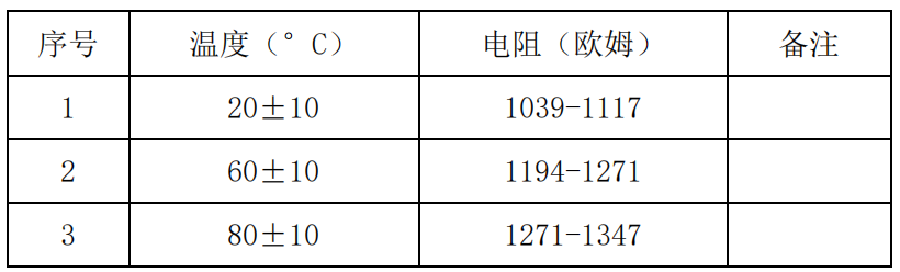
Set the multimeter's resistance range to 2000Ω, connect the test leads to the temperature sensor terminals (as shown below), and read the measured resistance. If the measured resistance is outside the specified range, zero resistance, or infinite resistance, replace the temperature sensor. Otherwise, check the sensor wiring harness (chassis wiring harness) for a short, break, or open circuit.
A. If the temperature sensor's electrical connector is damaged, the pin terminals are loose, or the connection is poor, replace the sensor.
B. If the temperature sensor's threaded connector is damaged, resulting in a poor seal, repair or replace the sensor as appropriate.
1.2.1When checking the temperature sensor's resistance, measure and record the ambient temperature and compare it to the reference value table.
1.2.2. Connectors or wiring harnesses must only be plugged in and out when power is off.
1.2.3. The normal supply voltage for the temperature sensor is 24V, with a maximum overload voltage of 30V/h.
1.2.4. The tightening torque for the temperature sensor installation is 28Nm ± 3Nm.
1.2.5. When installing the mating connector, the maximum tightening torque is 2.5Nm. When attaching the mating connector, avoid twisting the plastic threaded tube.
The yellow retarder fault indicator on the instrument panel illuminates; the retarder is inoperative. Read the fault codes: SPN744-5, 774-3.
A. Check the solenoid valve inside the proportional valve for damage. Set the multimeter's resistance range to 200 ohms. Connect the test leads to the two terminals of the proportional valve and read the resistance (see the figure below). At normal temperature and pressure, the standard resistance range for a proportional valve is 18-23 ohms. If it exceeds this range, the solenoid valve is considered damaged and the proportional valve should be replaced. If the resistance is normal, proceed to step B.
B. Check the wiring harness (chassis wiring harness) for a short circuit, a break, or an open circuit. If so, repair the wiring harness as appropriate. III.
The yellow retarder fault light on the instrument panel illuminates; the retarder operation is limited or inoperative. Read the fault code: SPN764.
If the instrument panel displays the SPN764 fault code, check the retarder pressure sensor. VOITH. The normal parameters of the retarder pressure sensor are shown in the table below.
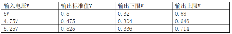
Under normal temperature and pressure, adjust the multimeter to the DC voltage position, set the DC power supply to 5V, and measure the sensor output voltage. If the measured value exceeds the range in the above table, the sensor is considered to be faulty. Please replace the pressure sensor. Otherwise, please check whether the sensor connection harness (chassis harness) has a short circuit, a break, or an open circuit fault.