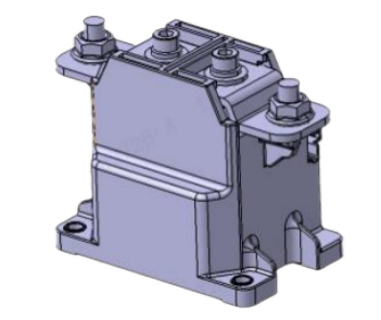
Relay Function Description
As a high-voltage on/off switching component, the contactor primarily controls the connection and disconnection of the charging and discharging circuits, controls the output and disconnection of high-voltage power from the pack, controls the charging process, and activates and deactivates the thermal management system. In the event of a battery self-protection fault or fire warning fault, it disconnects all high-voltage circuits to protect the battery and the vehicle.
1.1 Connect the debug harness and the host computer.
1.2 Power on the vehicle and check for a fault code indicating a stuck relay.
1.3 Remove the high-voltage box (junction box) from the vehicle and open the top cover. If a stuck main relay fault is reported, proceed to the next step. For any relay other than the main relay, proceed to step 5.
1.4 Disconnect the high-voltage wiring harnesses before and after the pre-charge relay.
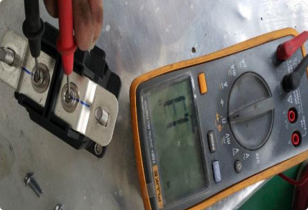
1.5 Use a multimeter to measure the resistance between the DC+ and DC- terminals of the relay (normally, it should be infinite). If the resistance is not infinite, proceed to the next step. If the resistance is normal, proceed to step 7.
1.6 If the heater relay is stuck, check the insulation and resistance of the heater circuit. If normal, replace the relay. If not, repair or replace it. Ensure the circuit is functioning properly before replacing the relay.
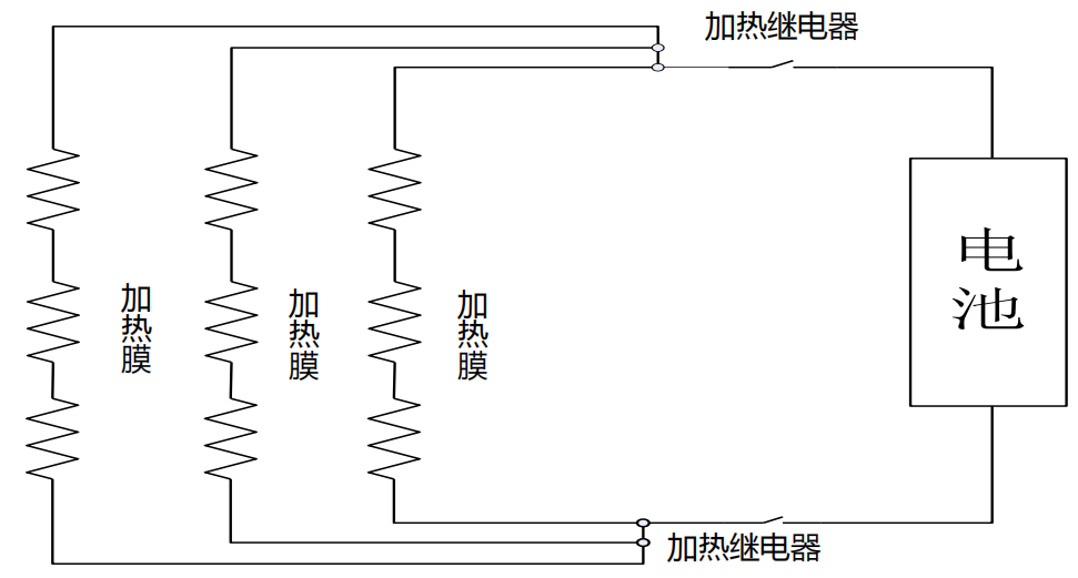
Heating Module Operating Principle:
When the heating start conditions are met, the BMS controls the heater relay to close, energizing the heating circuit and turning on the heater.
Heating film fault diagnosis criteria:
If the minimum average temperature rise of any CSC is ≤ 3°C for three consecutive times during continuous heating for 40 minutes,
2.1 Power on the vehicle and check for fault codes indicating a heating circuit or heating film fault. Verify the correct connection of the heating wire harness according to the electrical schematic.
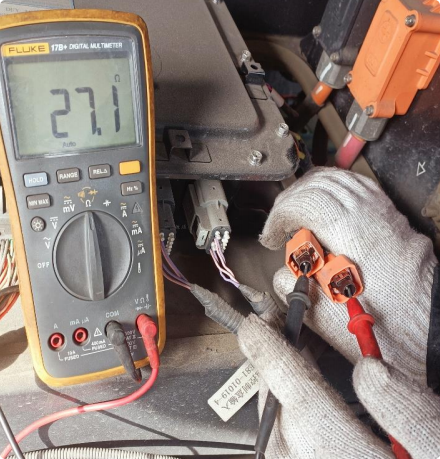
2.2 Power off the vehicle, disconnect the high-voltage MSD, disconnect the positive and negative connectors on the high-voltage heating module, and measure the resistance of the heating film with a multimeter.
2.3 Locate the abnormally resistant branch, identify the fault point in the heating circuit or the abnormally resistant electrical box, and repair the problem.
2.4 Check the heating wire harness for open circuits or poor contact.
Charging gun CC2 is 1k ohm to ground.
Charging base CC1 is 1k ohm to ground.
Charging base PE is continuous to ground.
120 ohm between S+ and S-.