1、Battery Charging Process and Related Messages
2.1.CC1 Detection Principle and Process
2.2.CC2 detection principle and process
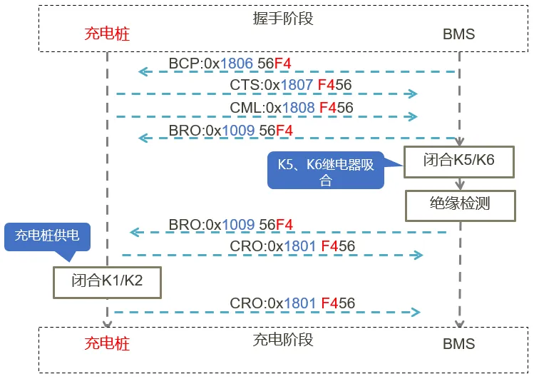
2.3.During the handshake phase
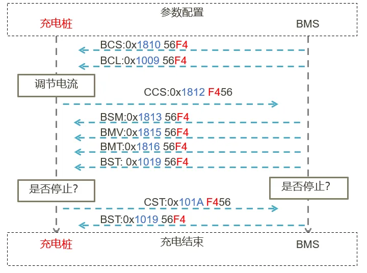
2.4.The parameter configuration phase
The charging process of a charging pile to the BMS goes through five stages.
physical connection:handshake, parameter configuration, charging, and termination.

CC1/CC2 Voltage Detection, Locking the Charging Pile, Closing K3/K4 to Output Auxiliary Power.
Handshake Message, Insulation Test, Discharge Voltage.
Sending Battery Charging Parameters, Closing K5/K6, Insulation Test, Closing K1/K2,.
Charging Phase Parameter Configuration.
Charging End/Statistical Data, Pressure Relief and Disconnecting K1/K2/K5/K6, Disconnecting K3/K4 to Disconnect Auxiliary Power, Unlocking the Charging Pile.
During the hardware connection (i.e., the circuit connection process when the charging pile is plugged into the charging socket), CC1 and CC2 are the key connection points.
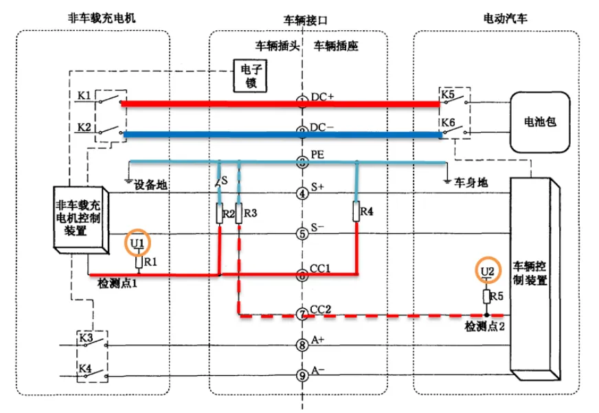
CC1 corresponds to charging pile detection point 1, which reports the CC1 voltage. In this circuit, R1, R2, and R4, the mechanical switch S, the blue (PE) and red colors in the diagram, and the U1 (12V) power supply are equivalent to the following circuit.
When the charging cable is not plugged into a charging socket, R4 is not connected to the detection circuit. When the mechanical switch is pressed, S opens, and the voltage at detection point C1 is the power supply voltage, i.e., 12V.
When the mechanical switch is released, S closes (normally closed). R1 and R2 are connected in series, and the voltage at detection point C1 is 6V. After the charging cable is plugged into the charging socket, if CC1 is properly connected, R4 is connected to the detection circuit. When the mechanical switch is pressed, S opens. R1 and R4 are connected in series, and the voltage at detection point CC1 is the power supply voltage, i.e., 6V.
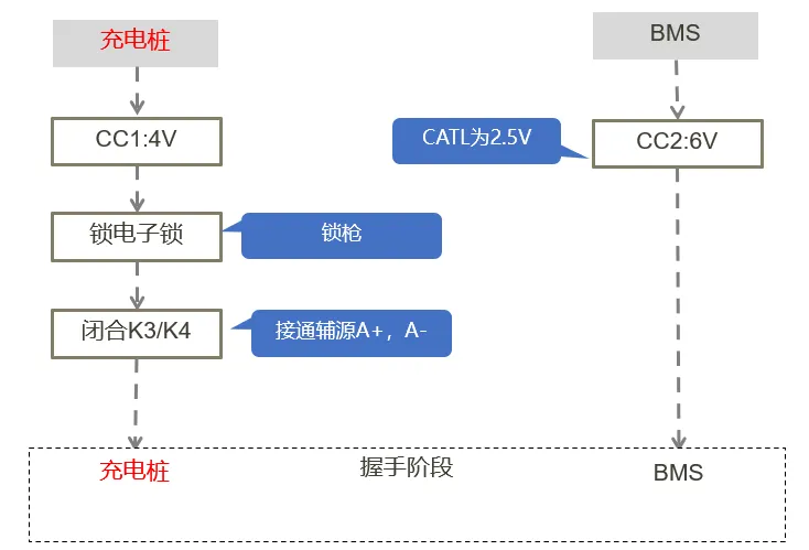
When the charging cable is inserted into the bottom of the socket, the mechanical switch automatically pops up, and S closes. R2 and R4 are connected in parallel, with a resistance equivalent to 500 ohms. They are then connected in series with R1, dividing the voltage at detection point CC1 to 4V.
Once the charging pile detects 4V at CC1, it outputs K3 and K4, closing them. K3 and K4 are the charging pile's 12V/24V auxiliary power relays. This connects the auxiliary power supply to the charging connector A+ and A-. This also wakes up the BMS and begins verifying the connection at monitoring point CC2.
CC2 corresponds to charging pile detection point 2, which provides feedback on the CC2 voltage. In this circuit, R3\R5, the blue (PE) and red (illustrated), and the U2 (5V) power supply are equivalent to the following circuit:
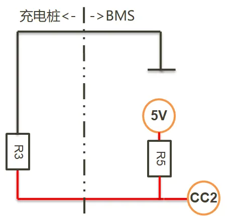
The Ningde BMS provides a 5V power supply, V2. When the charging plug is not plugged in, CC2 detects a voltage of 5V. After plugging in the charging plug, R3 and R5 are connected in series, and after voltage division, the voltage at detection point CC2 is 2.5V. Once the BMS detects 2.5V, it enters the charging handshake phase.
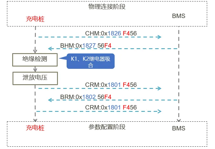
the charging pile sends a CHM (Charger Handshake Message). If the low-voltage control system is operating normally, the BMS responds with a BHM (BMS Handshake Message). After receiving this handshake message, the charging pile closes K1\K2 and performs an insulation test.
If the insulation test passes, the charging pile discharges the voltage and opens K1\K2. The charging pile sends a CRM (Charger Recognition Message), which the BMS receives and returns a vehicle identification BRM (Vehicle Recognition Message, BMS Identity Recognition Message).
The BMS then sends a vehicle information message in a multi-packet format, including the optional VIN charging information. If the charging pile successfully sends the CRM (Charger Recognition Message), with the first byte of the message data being 0xAA, the handshake is successful and the parameter configuration phase begins.
primarily involves the interaction and setting of charging parameters between the charging pile and the BMS. The BMS sends a BCP (battery charging parameter message) to the charging pile, and the charging pile sends CTS (charger time synchronization information) and CML (charger maximum output capability) to match the charging pile's shared capacity with the BMS battery charging parameters.
After the matching is complete, the BMS sends a BRO (battery charging readiness status), closes the charging contactor, and performs an insulation test on the BMS side. After the test is complete, it sends a BRO (battery charging readiness status message) with the first byte of the message data being 0xAA, indicating that the BMS is ready for charging. After receiving this information, the charging pile closes the high-voltage contactors K1\K2 on the charging pile side and sends a CRO (charger output readiness status message) with the first byte of the message data being 0xAA, indicating that the charging phase has begun.
During the charging phase, the BMS sends a BCL (Battery Charging Requirement) and a BCS (BMS Request to Send Multiple Packets) to the charging pile. The charging pile adjusts the charging current based on demand and provides feedback in the CCS (Charger Charging Status Message).
The BSM provides feedback in the form of BSM (Battery Status Information), BMV (Battery Cell Voltage Message), and BMT (Battery Temperature Message). By monitoring each status in real time, the BMS determines whether to terminate charging.
The BMS sends a BST (BMS Charge Termination Message) in the following situations: normal charging termination (SOC full, battery cell voltage reaches the specified level), abnormal termination (manual termination by the charging pile), or failure termination (insulation fault, communication fault, physical connection fault, overtemperature fault, etc.).
The charging pile sends a CST (Charger Charge Termination Message) in the following situations: normal charging termination (SOC full, battery cell voltage reaches the specified level), abnormal termination (manual termination by the charging pile), or failure termination (insulation fault, communication fault, physical connection fault, overtemperature fault, etc.). The charging process then enters the charging termination phase.
Upon entering the charging end phase, the BMS sends a BSD (BMS terminate charging message) and disconnects K5 and K6 (charger positive and negative contactors). The charging pile sends a CSD (charger terminate charging message) and disconnects K1 and K2 (charger high-voltage contactors). The charging pile executes the circuit discharge procedure to reduce the residual voltage in the charging pile module and circuit. It also disconnects K3 and K4 (disconnecting the A+ and A- wakeup power on the charging gun) and the charging gun electronic lock. The charging process ends.
The termination message contains charging information. If the termination is abnormal, a BEM (081E BMS error message) is sent, and the charging pile sends a CEM (081F charger error message). The associated message contains error information and the reason for the termination.
