The IGBT drive circuit of a pure electric vehicle consists of an upper and lower bridge.
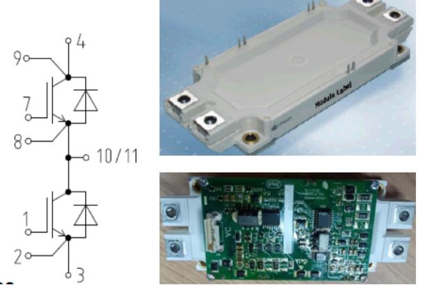
To use a digital multimeter to measure the three electrodes and the upper and lower arms of an IGBT, we first need to understand its basic circuit structure. Pins 3 and 4 of the IGBT can be determined by using a series diode and its forward voltage drop. As shown in the figure, pin 4 is connected to the battery's DC+ supply, while pin 3 is connected to the battery's DC- supply.
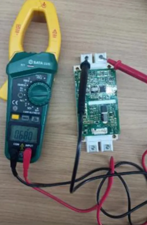
The measured voltage drop is 0.68V, indicating that the red test lead is connected to pin 3 of the IGBT and the black test lead is connected to pin 4.
We also know that pin 3 is the emitter of the lower arm, and pin 4 is the collector of the upper arm. The emitter of the upper arm and the collector of the lower arm are connected together and output as one phase of the three-phase AC power. This is measured using a multimeter.
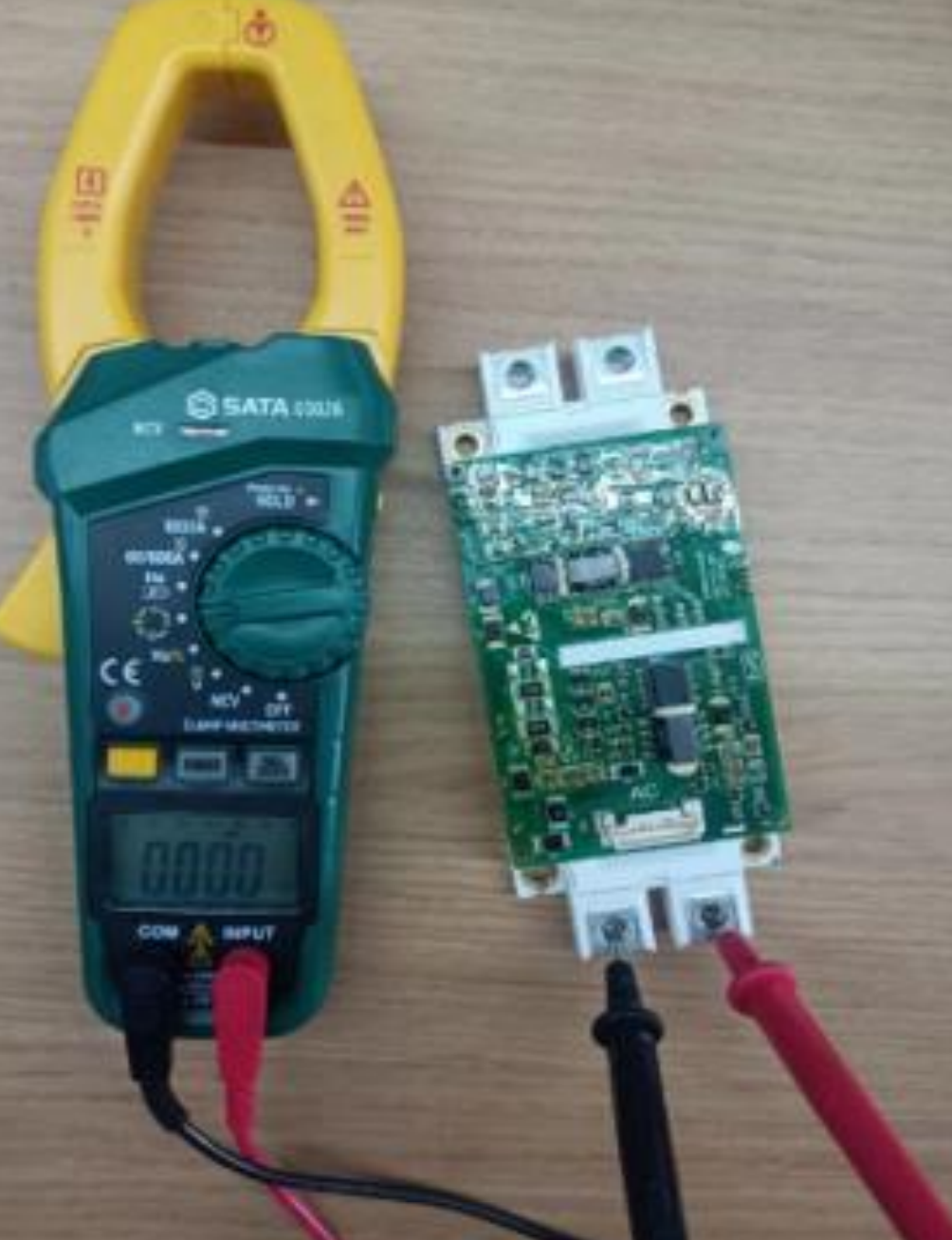
The measured voltage drop is 0V, indicating that the emitter of the upper bridge arm and the collector of the lower bridge arm are connected together, and the output is a single-phase AC current.