1、Automatic Transmission Self-Learning Preparation
2、Clutch Self-Learning Operation
3、Self-Learning Instrument Displays
4、Clutch System - Disassembly and Installation
5、Brake Assembly - Disassembly and Installation
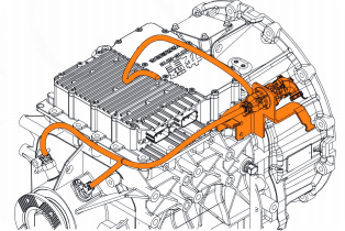
6、Main Transmission Shift Selector Actuator - Removal and Installation
Vehicle on level ground
Handbrake activated, engine idling, transmission powered on normally
Transmission in neutral, shift lever in neutral
Apply the footbrake;
Within 6 seconds, press the handle switch A/M four times and the switch E/P twice (press A/M first, then E/P).
Clutch self-learning begins. You can release the footbrake at this point.
Clutch self-learning completes. Power off and back on after 10 seconds.
If self-learning fails, power off and back on, check the self-learning preparation conditions, and then retry self-learning.
If self-learning is not in progress, during self-learning, or if self-learning fails: The instrument panel's "Idle Head" indicator will illuminate, indicating a green headlight.
If self-learning is successful: The instrument panel's "Idle Head" indicator will turn off.
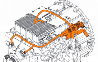
Disassemble the Transmission Assembly
Disconnect the Wiring Connector
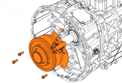
Disassemble the AMT Clutch Actuator Assembly
Clean components and mounting surfaces;
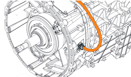
Replace the O-ring and install the AMT clutch actuator assembly; tighten to a torque of 40 ± 5 N·m. When installing the AMT clutch actuator assembly, push the clutch actuator in to bleed out the air inside.
Connect the wiring harness connector and secure with a cable tie;
Install the Transmission Assembly
Start the engine and perform a transmission auto-learn.
Disassemble the Transmission Assembly;
![]()
Disassemble the Steel Pipe Assembly - Transmission Shift Assist;
Remove the Brake Housing and remove the Piston, Dual Steel Plate, and other brake components.
Install the seal and piston. Slide the two seals onto the piston. The seal lips must be free of damage or flanging. Then install the piston into the brake housing, taking care not to damage the seal during installation.
Tighten the steel ball into the center groove of the piston with an installation pressure of 50-100N.
Install the O-ring onto the stop block, then install the stop block into the inner hole at the front end of the intermediate shaft with an installation pressure of 50-100N. Place the brake return spring into the inner hole of the stop block, then install the bushing.
Concentrically install the three steel plates and two friction plates into the grooves of the front housing, with the friction plates between the two steel plates. The installation sequence is shown in the figure. Ensure that the inner splines of the friction plates mate correctly with the splines of the intermediate shaft. The three protruding claws of the steel plates rest in the corresponding grooves of the front housing.
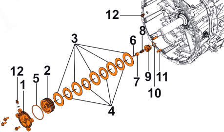
Install the brake assembly and its sealing gasket into the intermediate shaft bearing hole on the front housing, ensuring that the ribs of the sealing gasket face the actuator housing.
Turn off the main power switch;
Mark and remove the wiring harness assembly;
Disconnect the air pipe and remove the pipe joint;
Remove the AMT main transmission shift selector actuator assembly.
Clean the components and mounting surfaces. Inspect the shift selector actuator for proper assembly and ensure the actuator assembly is free of any scratches or stains.
Replace the gasket and install the AMT main transmission shift selector actuator assembly.
![]()
Determine the position of each shift selector fork, including the rear auxiliary cylinder shaft, ensuring that each fork aligns with the gear sleeve in the main transmission case and that the rear auxiliary cylinder shaft coupling aligns with the groove on the rear auxiliary shift fork shaft. Position the sealing gasket, paying attention to the orientation of the gasket ribs. Gently rock the actuator during installation; avoid using brute force. After installation, tap the locating pins with a rubber hammer to ensure they are fully seated against the center housing. Tightening torque: 80 ± 5 N·m
Install the pipe fitting and connect the air pipe.
Install the wiring harness assembly and connect the wiring harness connectors.
Start the engine and perform a transmission auto-learn.