
The following gears in the gear train need to be timed:
Intake camshaft gear Exhaust camshaft gear Gear timing assembly points:
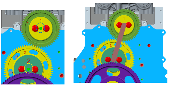
Align mark "0" between the crankshaft timing gear and the double-stage gear, see Figure 1;
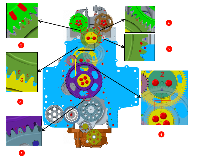
Align mark "2" between the double-stage gear and the second idler gear of the camshaft, see Figure 6;
Align mark "3" between the first idler gear of the camshaft and the second idler gear of the camshaft, see Figure 2;
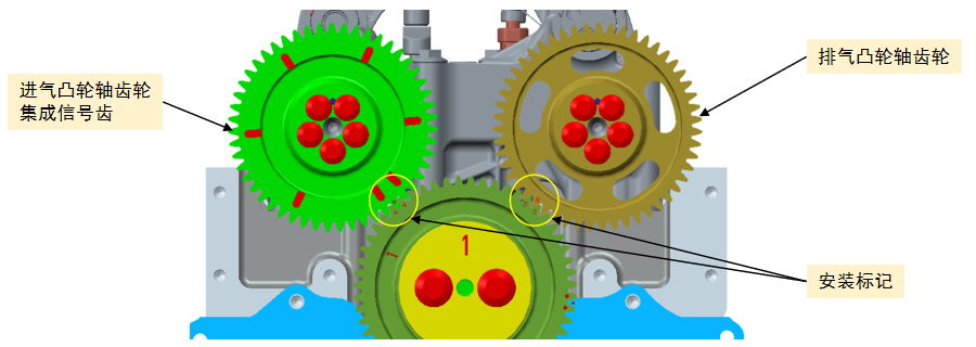
Align mark "4" between the intake camshaft gear and the first idler gear of the camshaft, see Figure 3;
Align mark "5" between the exhaust camshaft gear and the first idler gear of the camshaft, see Figure 4;
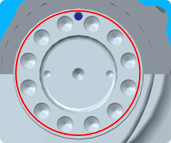
Crankshaft gear assembly Adjust the crankshaft to the top dead center position of cylinder 1 (the locating pin is at the 12 o'clock direction) and keep it stationary;
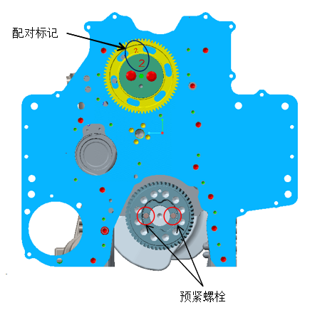
Apply anaerobic flat sealant to the outer ring of the crankshaft Install the crankshaft gear and preliminarily secure it with two pre-tightening bolts (Q218B0840-0H1) and tighten it to 24±4N.m;
Camshaft second idler gear assembly Assemble the wheel hub marked "2" and the camshaft second idler gear assembly marked "2" together;
observe the position of the cylinder block locating pin through the locating pin hole on the wheel hub, and quickly assemble the wheel hub and gear onto the locating pin to fit it with the rear end plate; Install the bolt Q1841235-0H1 and tighten it preliminarily with a tightening torque of ≤10N.m.
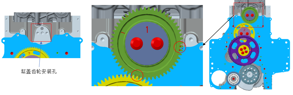
Assembly of the first idler gear of the camshaft Assemble the hub marked "1" with the first idler gear assembly of the camshaft marked "1" together; Align the mark "3" on the first idler gear of the camshaft with the mark "3" on the second idler gear of the camshaft, and install the hub locating boss into the cylinder head locating hole. Install two of them and tighten them crosswise to 100±15Nm
Install one end of the backlash adjustment tool in the center hole of the hub marked "1" and the other end in the center hole of the hub marked "2";
Tighten the mounting bolts of the second idler gear hub of the camshaft crosswise, first tightening them to 25±3Nm and then tightening them to 110±5Nm. Assembly of intake and exhaust camshaft gears The intake camshaft gear is positioned with a cylindrical pin Q5220414. The timing mark "4" is aligned with the timing mark "4" of the first idler gear of the camshaft. Fix it with 5 pins with a torque of 32±5%Nm;
The timing mark "5" of the exhaust camshaft gear and the rest are the same as the intake camshaft gear; Check the tooth side clearance between the first idler gear of the camshaft and the intake and exhaust camshaft gears, which should be 0.076~0.205mm.