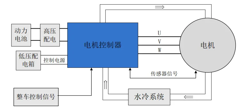
2、Functional Description of Each Component and Circuit
As a key power component in electric vehicles, the controller exchanges commands and status information with the entire vehicle via the CAN network. The controller collects motor current, speed, and position signals, integrates system status with vehicle control commands, and inverts the DC power from the vehicle's high-voltage distribution system into AC power to drive the motor.
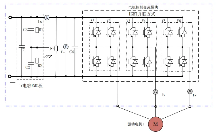
The main circuit of the controller is shown in the figure. It consists of a DC current sensor IS, a voltage acquisition circuit V1 (integrated on the control board), a discharge resistor R3, a support capacitor C4, motor controller converter modules V1-V6, AC current sensors ISV and ISW, Y capacitors C2-C3, X capacitor C1, intermediate resistors R1-R2, electrical connections, and busbars.
After the high-voltage DC power supply is disconnected, the discharge resistor discharges the charge on the support capacitor to prevent electric shock.
Stabilizes the DC voltage and provides capacitive reactive power to the motor.
Detects the DC current flowing into the controller.
Detects the V and W phase currents of the motor.
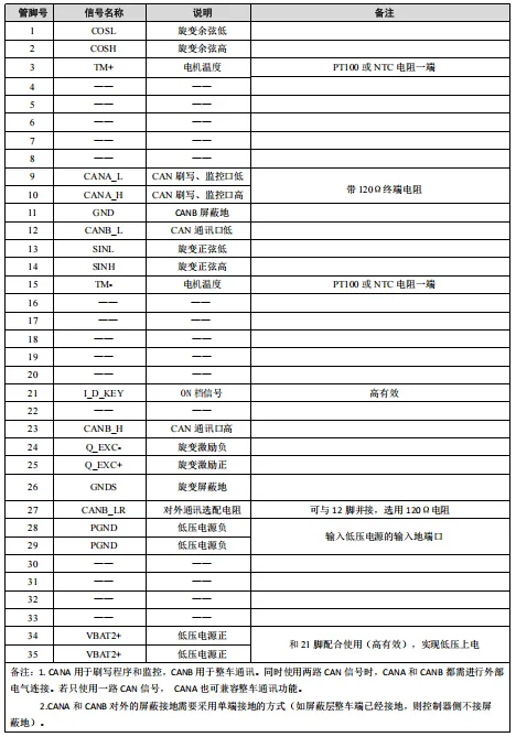
Controller external interface: X1 is the motor controller's low-voltage electrical interface.
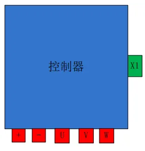
As shown in the figure, the controller's electrical interface consists of a power cable interface and a control cable interface. The +, -, U, V, and W power cable ends are crimped with matching copper wire rings and marked with the corresponding wire number. They are then bolted to the copper busbars of the various components.