2、Structural Principle and Operating Principle
The AMT clutch system is an electronically controlled, pneumatically assisted clutch system. In manual or automatic mode, the TCU controls the clutch actuator to engage and disengage the clutch assembly. AMT vehicles have no clutch pedal in the cab; the clutch is fully controlled by the TCU, reducing driver workload. The AMT clutch system consists of two main components.
The AMT clutch actuator receives commands from the TCU to control the engagement and disengagement of the clutch assembly and the clutch self-learning function; it also collects real-time information required for closed-loop control.
The structure and operating principle are similar to those of the pull-type clutch assembly in a manual transmission (MT).
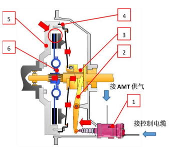
2.1.1 Clutch actuator assembly,
2.1.2 Transmission release mechanism,
2.1.3 Release bearing assembly,
2.1.4 Clutch cover and pressure plate assembly,
2.1.5 Flywheel,
2.1.6 Clutch driven plate assembly.
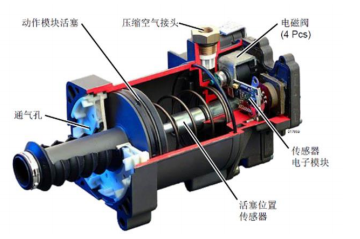
The clutch actuator primarily consists of a cylinder, an electronic control module, four solenoid valves, an actuating piston, a position sensor, and an air intake connector.
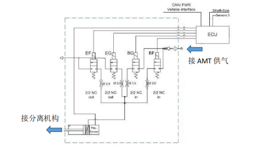
Two closing control solenoid valves have different diameters. The larger valve is used for rapid clutch engagement, while the smaller valve is used for slow clutch engagement. Two release control solenoid valves, also with different diameters, are used to achieve rapid and slow clutch disengagement. When the clutch system is operating, the clutch actuator receives status requests from the ECU and opens or closes the corresponding solenoid valves. The clutch actuator piston moves forward or backward, driving the release fork, thereby disengaging or engaging the clutch assembly and enabling vehicle starting, stopping, shifting, and creep mode.
3.1 Disconnect the clutch actuator connecting pipes and wiring harness.
3.2 Unscrew the clutch actuator bleed plug to release any residual air in the booster.
3.3 Remove the clutch actuator mounting bolts and push rod.
3.4 Before removing the clutch assembly, open the clutch retaining ring through the inspection port.
3.5 Remove the transmission assembly.
3.6 When removing the clutch, use a guide shaft to prevent the driven plate from falling.
3.7 Remove the clutch cover and pressure plate assembly fastening bolts and lower the clutch cover and pressure plate assembly.
3.8 Remove the clutch driven plate assembly.
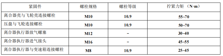
Tighten to the required torque.