2、Physical characteristics of the CAN bus
CAN, short for Controller Area Network (hereinafter referred to as CAN), is an ISO-standardized serial communication protocol. In the automotive industry, driven by the demands for safety, comfort, convenience, low power consumption, and low cost, a wide variety of electronic control systems have been developed.
Due to the varying types of data and reliability requirements for communication between these systems, multiple buses are often used, increasing the number of wiring harnesses.
To meet the needs of reducing the number of wiring harnesses and enabling high-speed communication of large amounts of data across multiple LANs, German electrical manufacturer Bosch developed the automotive-specific CAN serial communication protocol in 1986. CAN has since been standardized through ISO 11898 and ISO 11519 and has become the standard protocol for automotive networks in Europe.
Serial communication: Features: Only one data channel, transmitting signals in sequence.
Parallel communication: Features: Multiple data channels, capable of transmitting multiple signals simultaneously.
Connecting different electronic devices in the vehicle through two wires to form a local network.
Note: Bus devices are connected in parallel, broadcast transmission (only one controller sends data at the same time, and the other controllers read data).
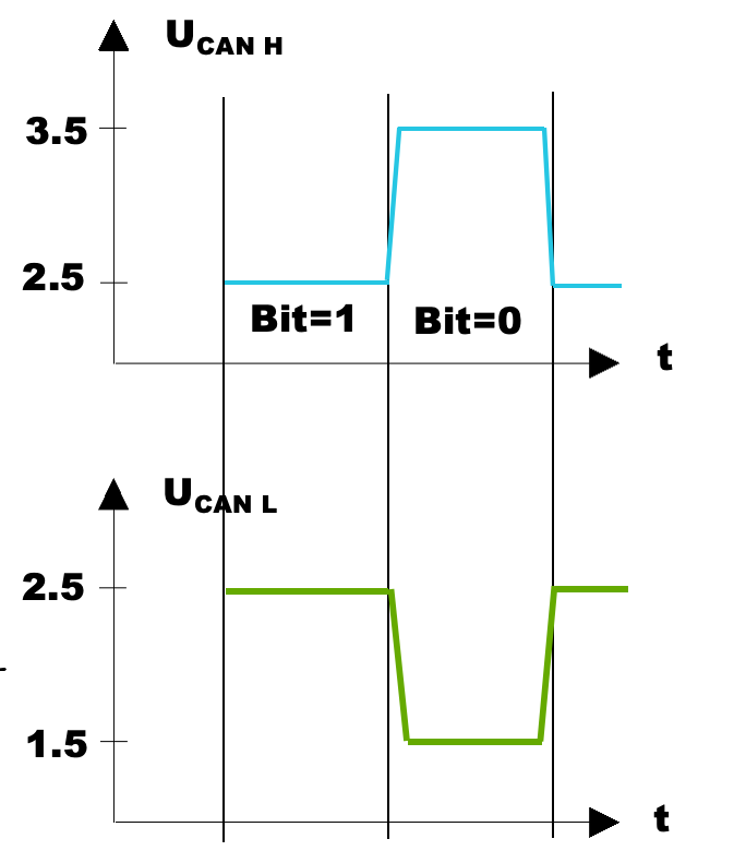
The CAN bus signal is a differential signal: U = UCAN H – UCAN L. The CAN bus expresses binary 0 and 1 by determining the voltage value of the CAN bus signal. That is, when the bus signal is 2V, it expresses binary 0; when the bus signal is 0V, it expresses binary 1.
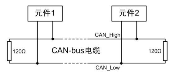
A 120-ohm resistor is connected at each end of the CAN bus network. Because it is connected in parallel, the bus resistance is 60 ohms.
The function of the terminal resistor is to absorb signal reflections and echoes. If the impedance is discontinuous and mismatched, signal reflections will occur, thereby interfering with the transmitted signal.
If the terminal resistor is added to two separate wires, it is equivalent to an open loop. This connection method will cause the impedance on the single wire to be more discontinuous, suddenly becoming 0 at the end, causing reflections to increase exponentially.
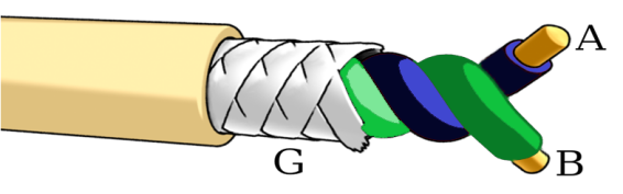
The CAN bus uses shielded twisted-pair cables, meaning the twisted pair is surrounded by a shield. The shield has only one ground point, known as the shield point. This is because the charge distribution of the vehicle's ground is uneven, resulting in potential differences across the vehicle's frame. Multiple grounding points can directly generate voltage differences, causing currents to flow through the shield and thus interfere with the CAN bus.
As a fieldbus, each node on the CAN bus can simultaneously detect data being transmitted on the network. When the bus is idle, each node can initiate its own message transmission. If multiple nodes simultaneously initiate message transmission requests, the arbitration mechanism determines which node will occupy the bus.
When a logic "1" is written to the bus, both CANH and CANL are at 2.5V, a "recessive" state. When a logic "0" is written to the bus, CANH is pulled up to 3.5V and CANL is pulled down to 1.5V, a "dominant" state. If a dominant bit and a recessive bit are written to the bus simultaneously by different nodes, the bus will appear to be dominant. This "dominant bit overriding the recessive bit" is the basis for conflict detection on the CAN bus.
When nodes begin transmitting their respective messages, if a node writes a recessive bit and reads back a dominant bit, the node will know that another higher-priority node is occupying the bus. It will then stop transmitting and continue receiving messages from the bus. This technique is called "non-destructive bit-by-bit" arbitration.